Download scientific diagram | The exploded diagram of the worm gear box assembly. The parts are as follows: 1-cover; 2-bearing; 3-worm shaft; 4-cover; 5-bearing; 6-gear box body; 7-bearing; 8-oil seal; 9-cover; 10-plug; 11-worm gear rim; 12-worm gear hub; 13-output shaft; 14-bearing; 15-oil seal; 16-cover from publication: Image-assisted collision detection for calculation of an assembly interference matrix | The assembly interference matrix is a foundational information model for assembly process planning such as assembly sequence and assembly path planning, and supports digital assembly simulation, intelligent assembly, digital twin-based assembly, and so on. The assembly | Collision Detection, Assembly and Matrix | ResearchGate, the professional network for scientists.

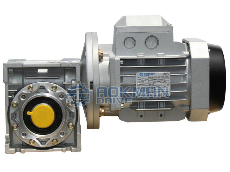
Gearbox - an overview

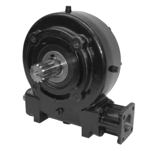
slewing ring bearing drive Tracking system, Driving, Engineering tools

The exploded diagram of the worm gear box assembly. The parts are as

Assembly exercise: spur and worm gear (MT 123) – Material Testing Laboratory Equipment
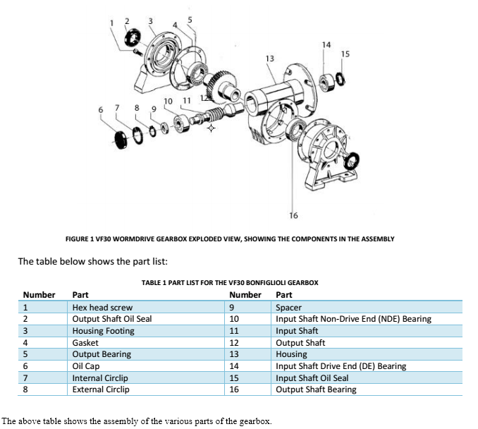
Solved 15 13 10 11 6 7 8 9 FIGURE 1 VF30 WORMDRIVE GEARBOX

The exploded diagram of the worm gear box assembly. The parts are as

Murray 1696675-00 - C950-52592-1, Craftsman 21.0 Gross TP 30 Dual Stage Snow Thrower (2017) Parts Diagram for Gear Case Assembly (704027)
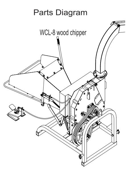
Parts Diagram - Chippers Direct

Exploded Diagram Stock Illustrations – 189 Exploded Diagram Stock Illustrations, Vectors & Clipart - Dreamstime